The Yagi on Mount Kanozan, AVANT 1
Original: Ryota / JJ1WTL — 519469435 · Original Japanese HTML
Published: 2026-02-08T17:50:00+09:00
English translation of the archived article text. The author’s first-person observations, uncertainty and later additions are preserved; this is not the research summary. Image contents are preserved as images, not silently incorporated into the translated prose.
A visit to a new experimental HF digital fixed station. First, the opening ten minutes, forty seconds, zero frames.
Strategy
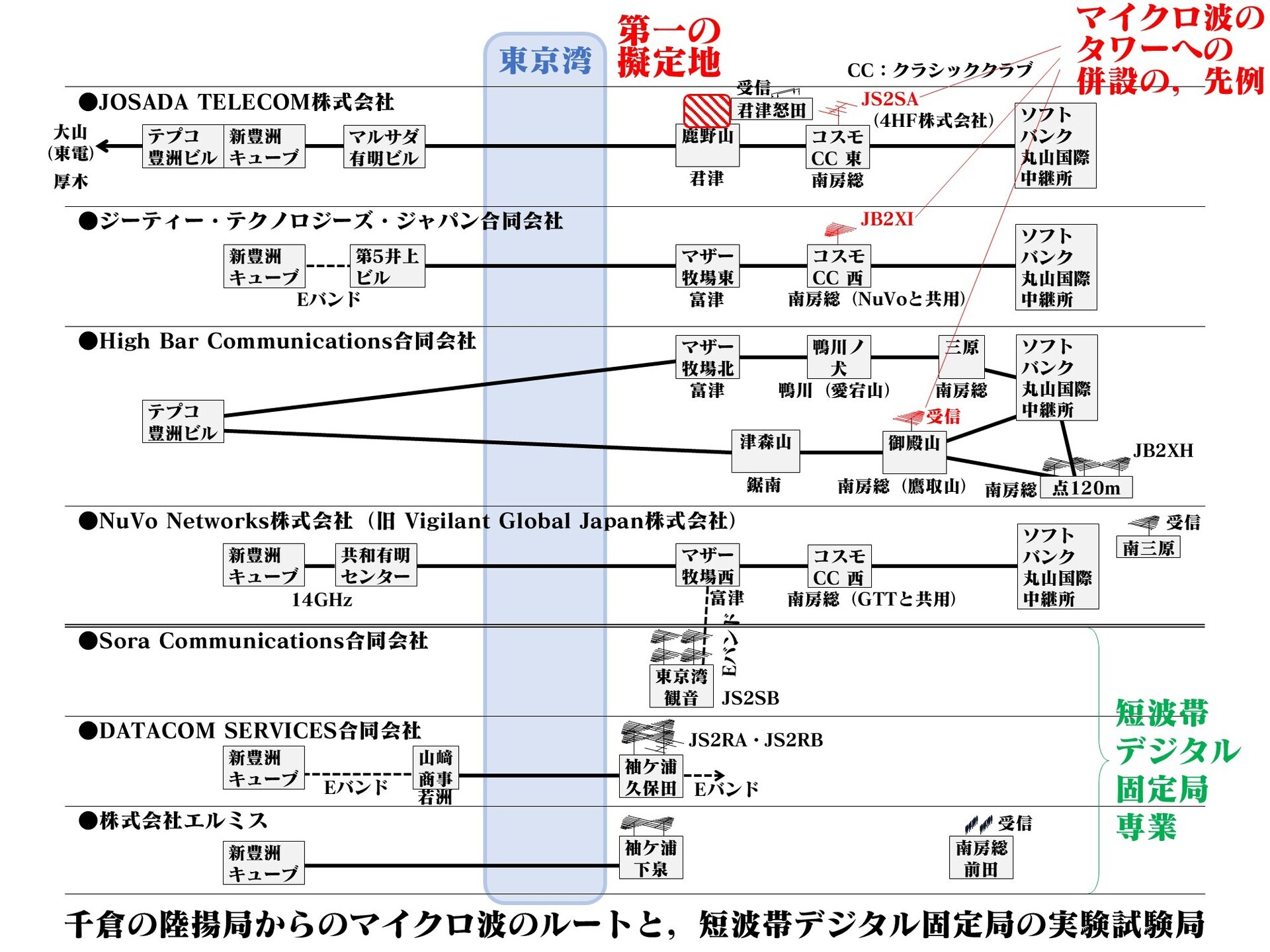
Where will JOSADA TELECOM establish its transmitting site? Its receiving site is already known.
First, assume use of an existing company-owned microwave tower.
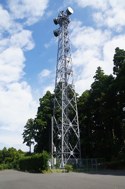
That makes Mount Kanozan the leading candidate; click to enlarge.
https://www.tele.soumu.go.jp/musen/SearchServlet?pageID=4&IT=A&DFCD=0003928888&DD=1&styleNumber=21
https://www.google.com/maps/@35.2531303,139.9635477,52m/data=!3m1!1e3
Concerns
Even so, some doubts remain about this assumption.
Homes are nearby
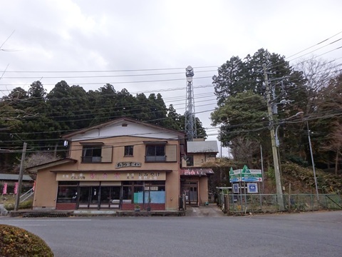
On an exposed ridge
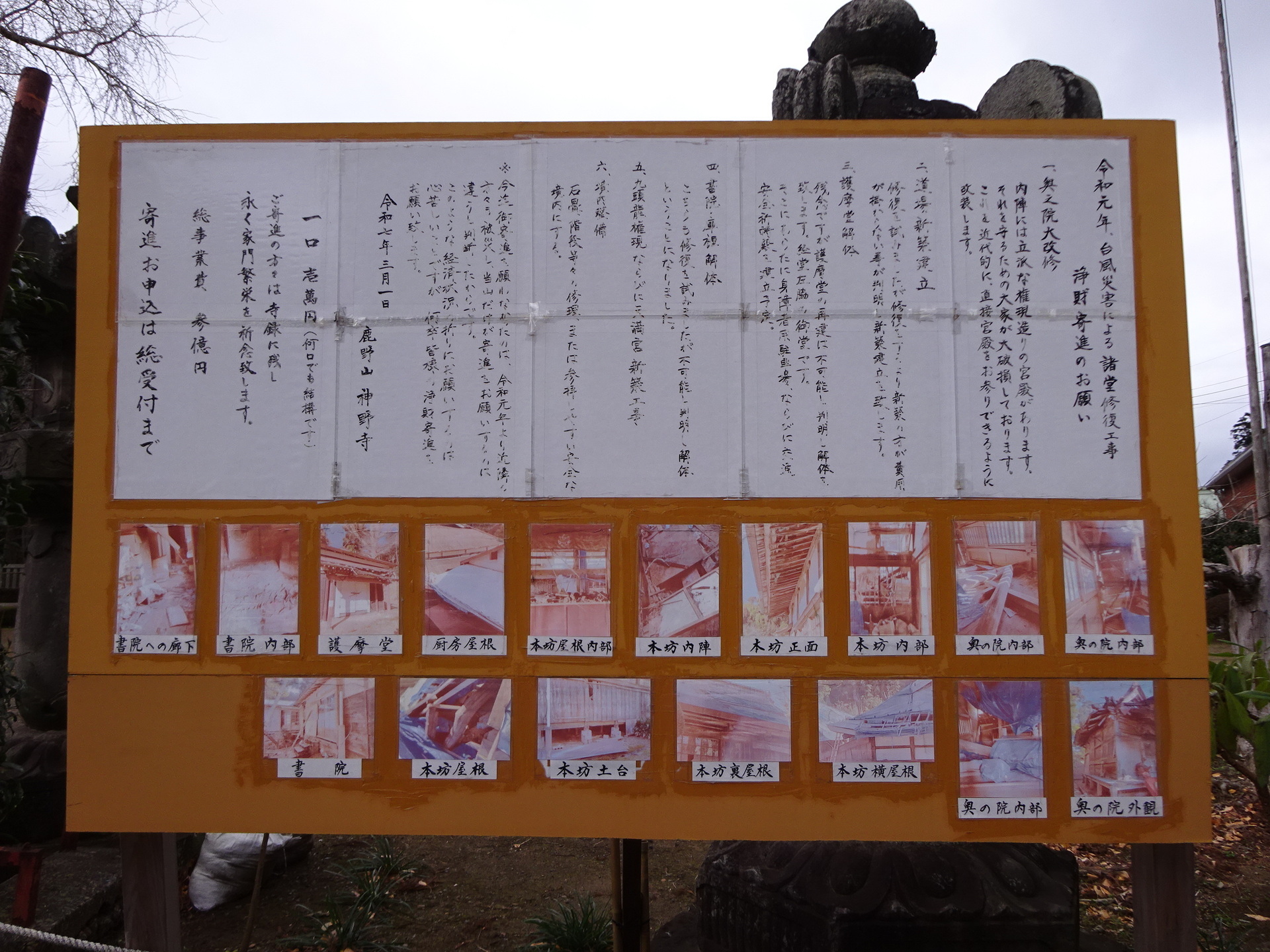
Elevation 359 m. Typhoon Faxai, the 2019 Boso Peninsula typhoon, damaged Jinyaji Temple at the foot of the tower.
Total restoration cost: ¥300 million. The temple's appeal for donations below; click to enlarge.
Plan B
Even if that guess is wrong, presumably a microwave/millimetre-wave branch will be built.
Then its antenna bearing will let us narrow down the site.
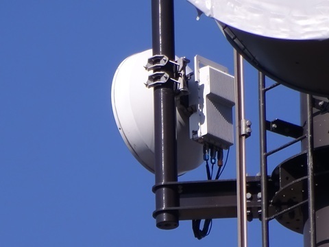
The photo below is NuVo Networks' Mother Farm example.
Its counterpart is JS2SB, Sora Communications, beside Tokyo Bay Kannon.
But that strategy requires considering not just Mount Kanozan but other relay points too:
-
SoftBank Maruyama International Relay Station.
-
Cosmo Classic Club.
Those would also be candidates.
…So the watch begins
Incidentally, each way takes over three hours and costs ¥2,274.
2025-09-14
No HF antenna added… defeated.
2025-11-02
?
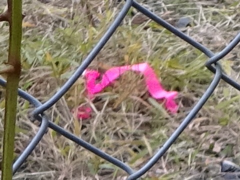
Pegs with pink tape tied to them, within the blue boxes. Arranged in a perfect rectangle, too.
Vacant ground opposite the existing microwave rack.
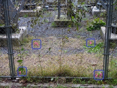
…Suspicious.
2025-11-15
The grass has been cut.
Part of regular maintenance,
or preparations for construction?
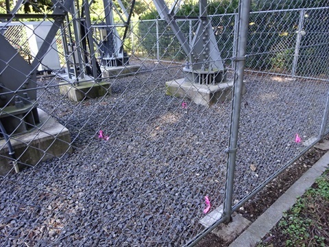
The pink-taped pegs remain. Suspicious.
2025-11-30
No change. Defeated.
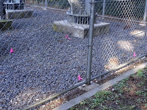
2025-12-13
!
A hut has appeared! I missed the celebratory mochi throwing.
Additional conduit has been laid too.
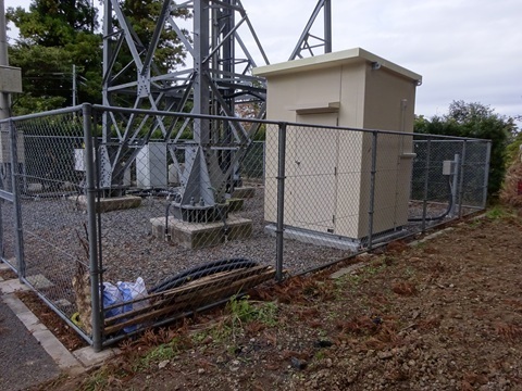
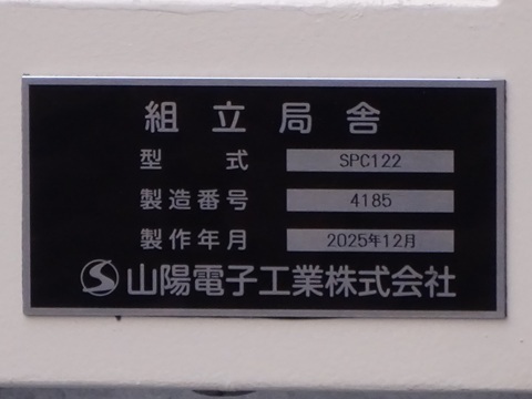
Read the nameplate: basic practice.
Made by Sanyo Electronics.
The HF antenna is not mounted yet.
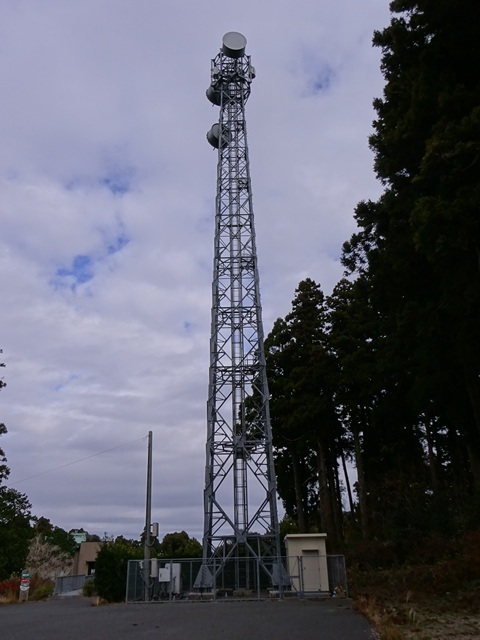
The location is settled, then.
Making people install an antenna on an exposed 359 m ridge in midwinter—how inhumane. At least the lightning risk is lower.
2025-12-20
I shortened the polling interval.
But it backfired. No change; defeated. 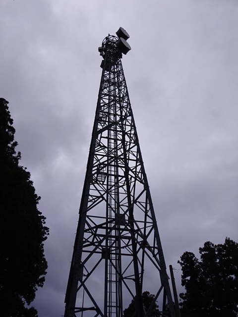
2025-12-28
Final visit of the year.
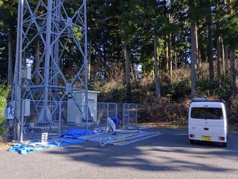
Oh! Work in progress, in fine weather, but on a Sunday.
A van with Hachioji plates beside it.
Don't the motorway tolls wipe out your profit?
They said it would still take a while.
2026-01-10
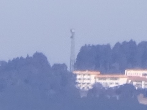
For reasons of my own, from Cosmo Classic Club, the microwave counterpart to the south.
Maximum zoom, 15.9 km north. A 12.7 cm gun could reach it.
How does it look… apparently not yet.
2026-01-25
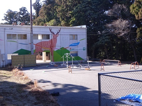
A Yagi has sprouted from the Forest Spirit's footprints.
Assembly in full swing
The workshop is open.
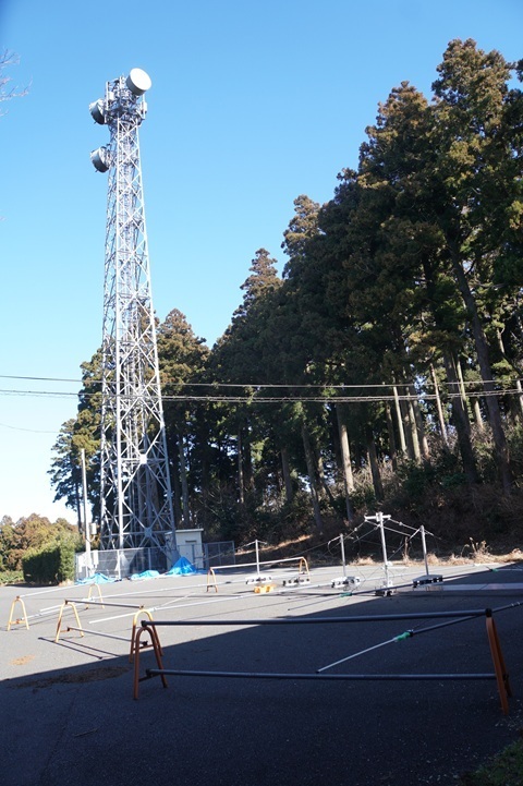
The parts.
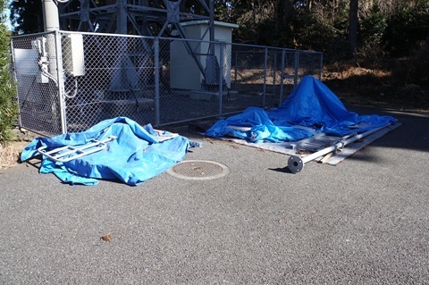
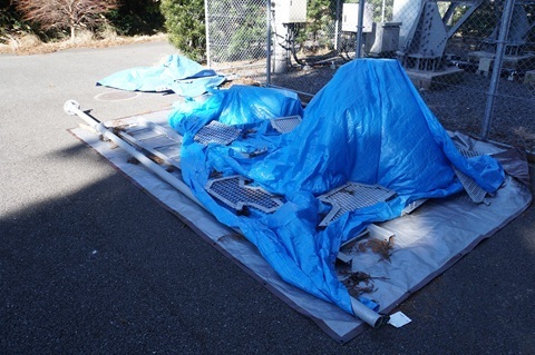
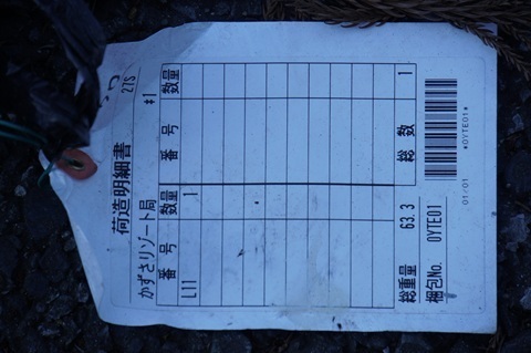
The official station name appears to be ‘Kazusa Resort station’, after the closed hotel.
Overall view
Once mounted, it cannot be examined like this. Seizing the opportunity…
Click this section's photographs to enlarge, up to 3.7 MB.
From the front.
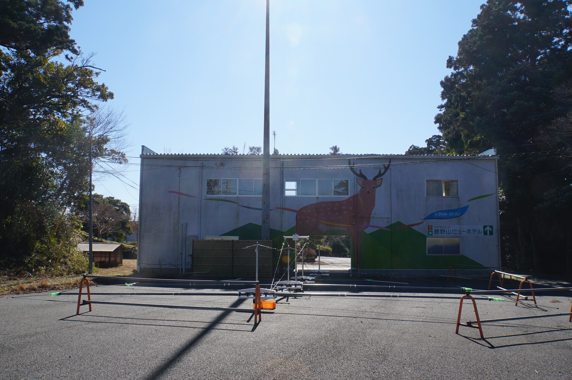
From the front right.
The second element from the front has not been attached yet.
Five elements.
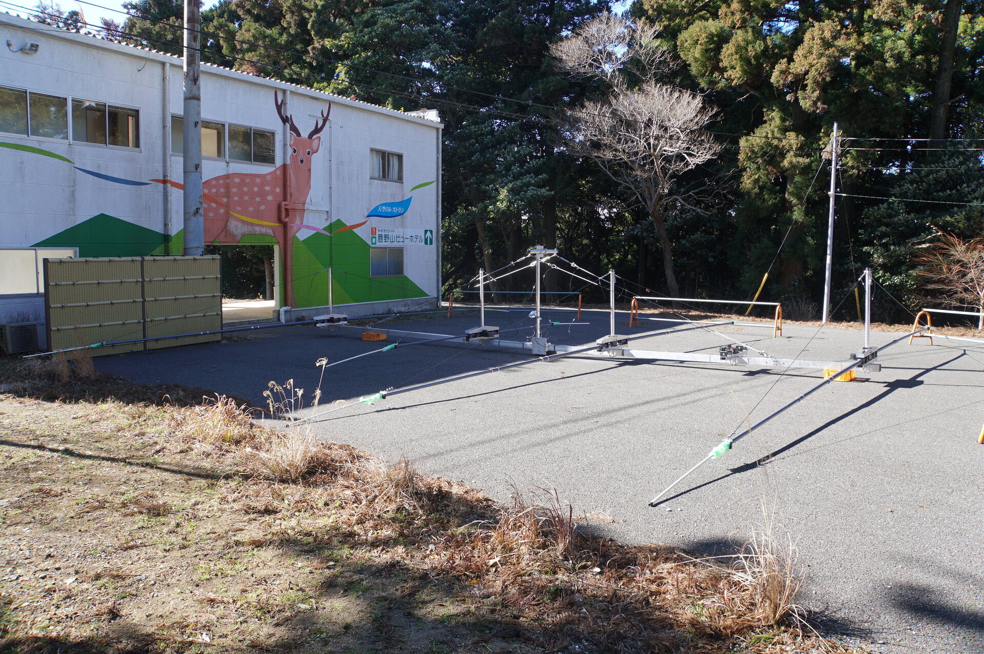
From the side. Boom length: nineteen paces.
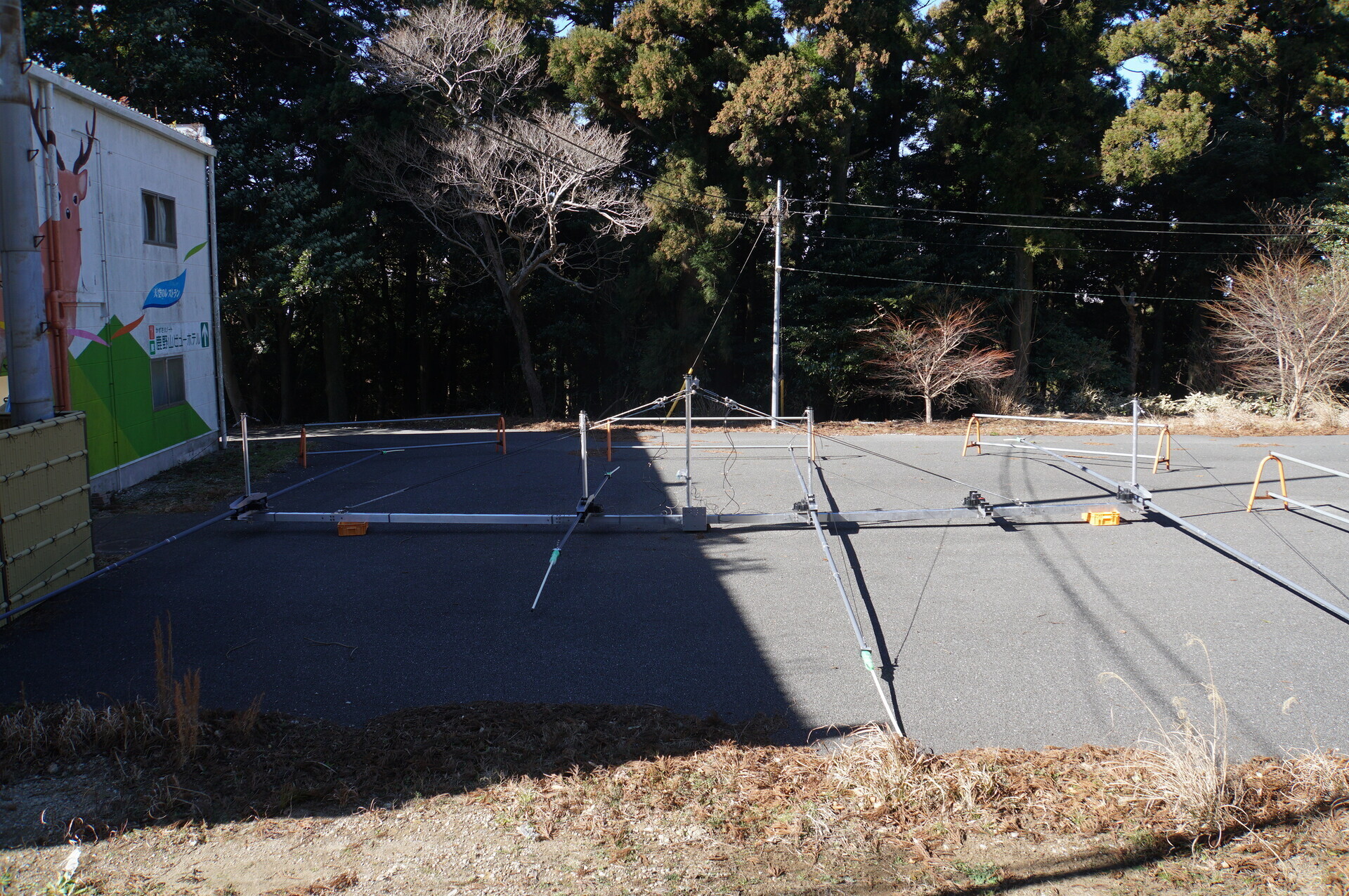
From the rear left.
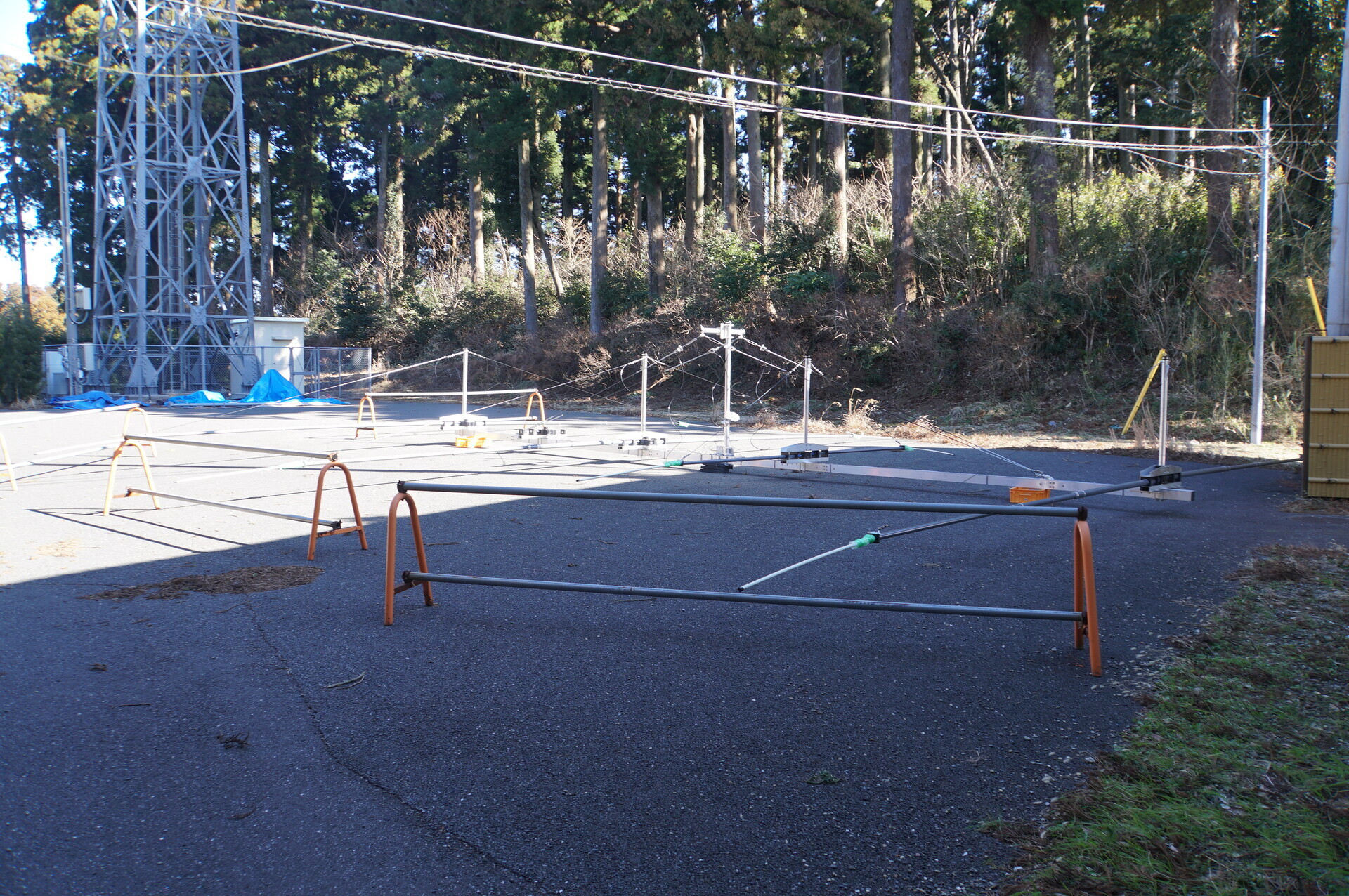
From behind.
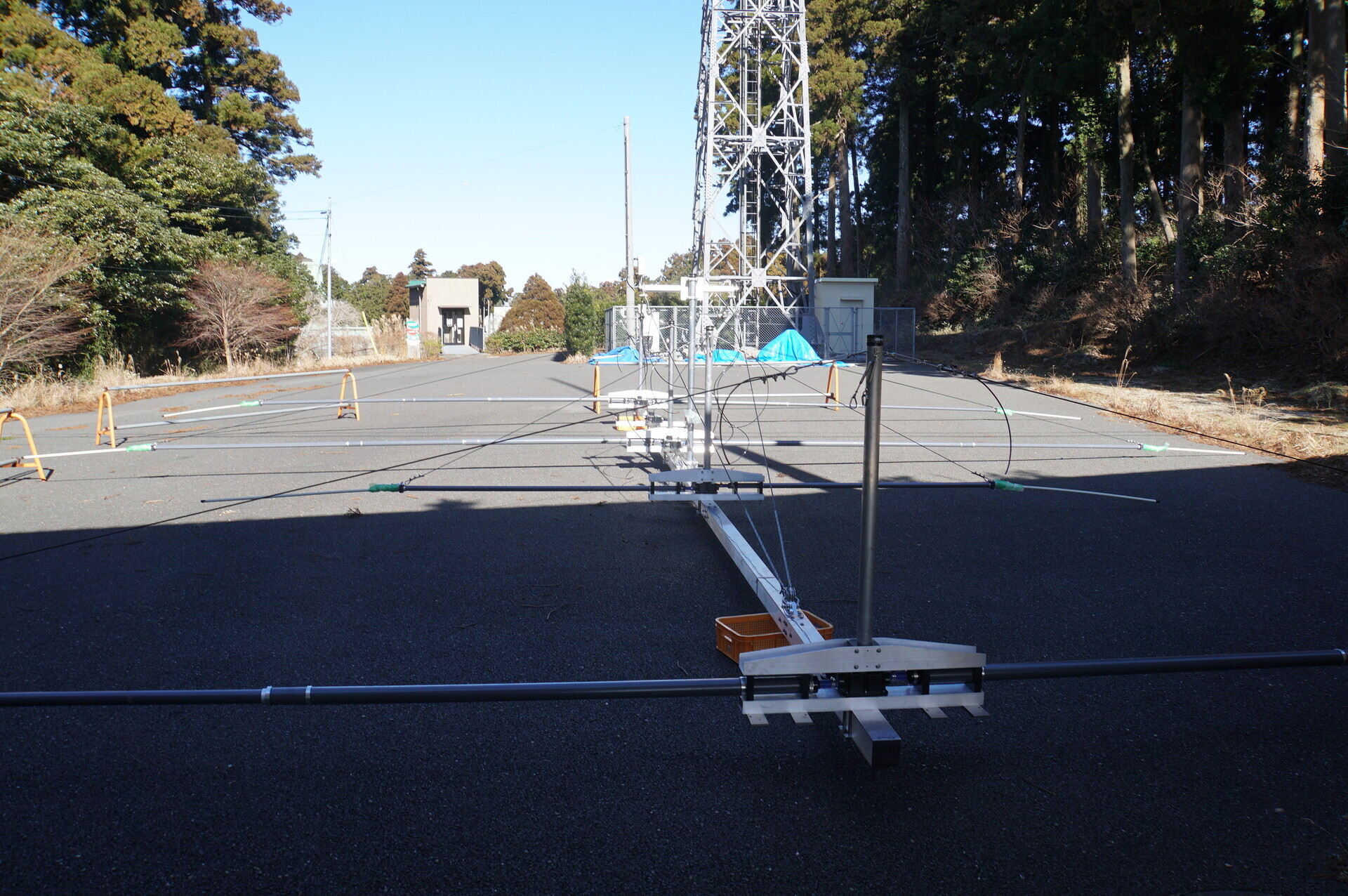
…This must be SteppIR's non-‘tape-measure’ model:
HFT540C.
『HFT540C Yagi Data Sheet』
https://steppir.com/wp-content/uploads/2023/10/HFT540C-Data-Sheet-3.2.pdf
『HFT540C Assembly Manual』
https://steppir.com/wp-content/uploads/2022/06/HFT540C-Assembly-Manual_7-23-21_2.0.4.pdf
Even without the tape-measure mechanism, it is multiband:
-
6.8–13.315 MHz: feeds the third, longer element.
-
13.315–30 MHz: feeds the fourth, shorter element.
Individual parts below
These photographs also enlarge when clicked. Enjoy, enthusiasts.
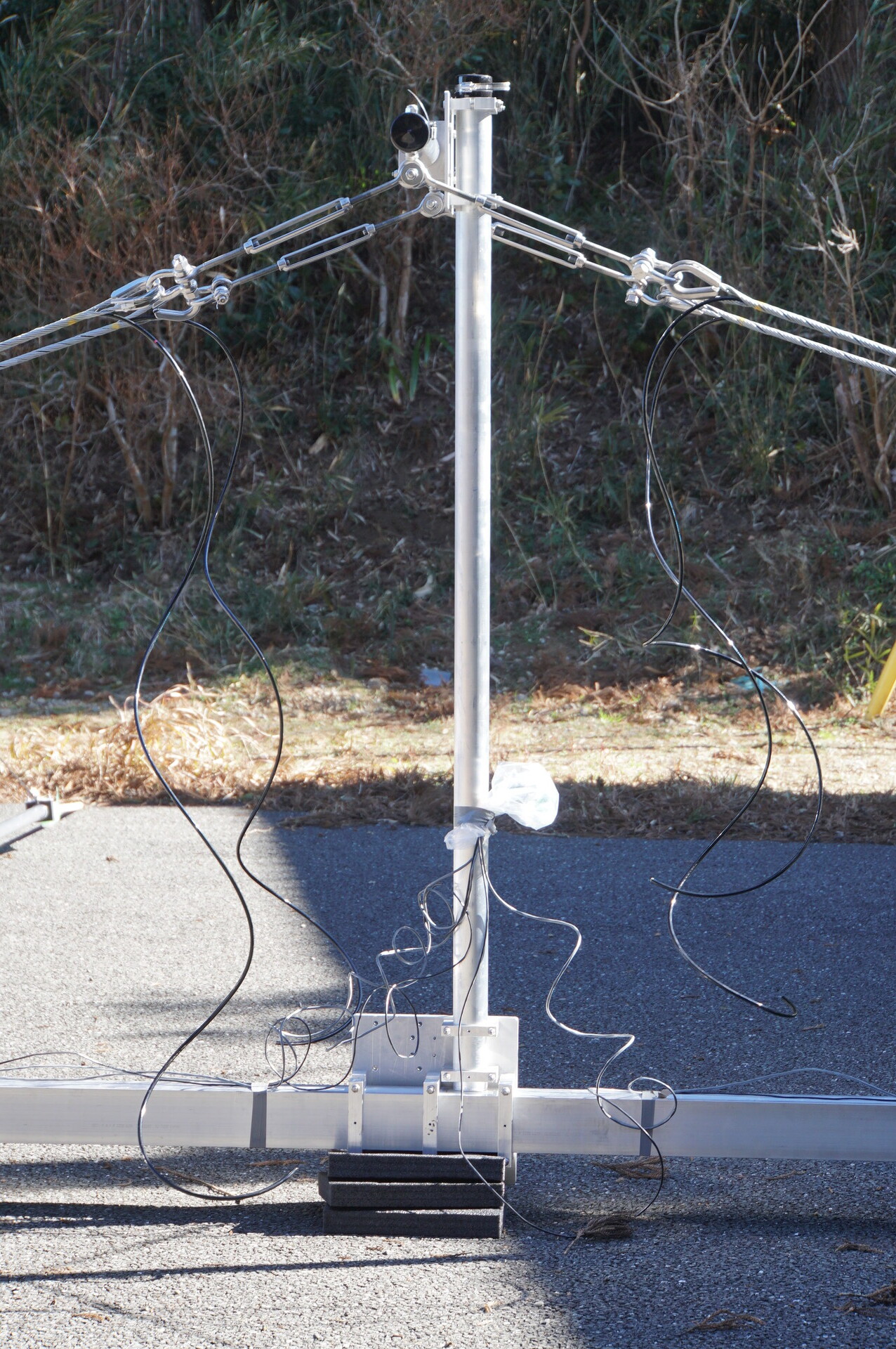
Mast
Supports the entire antenna, over 200 kg.
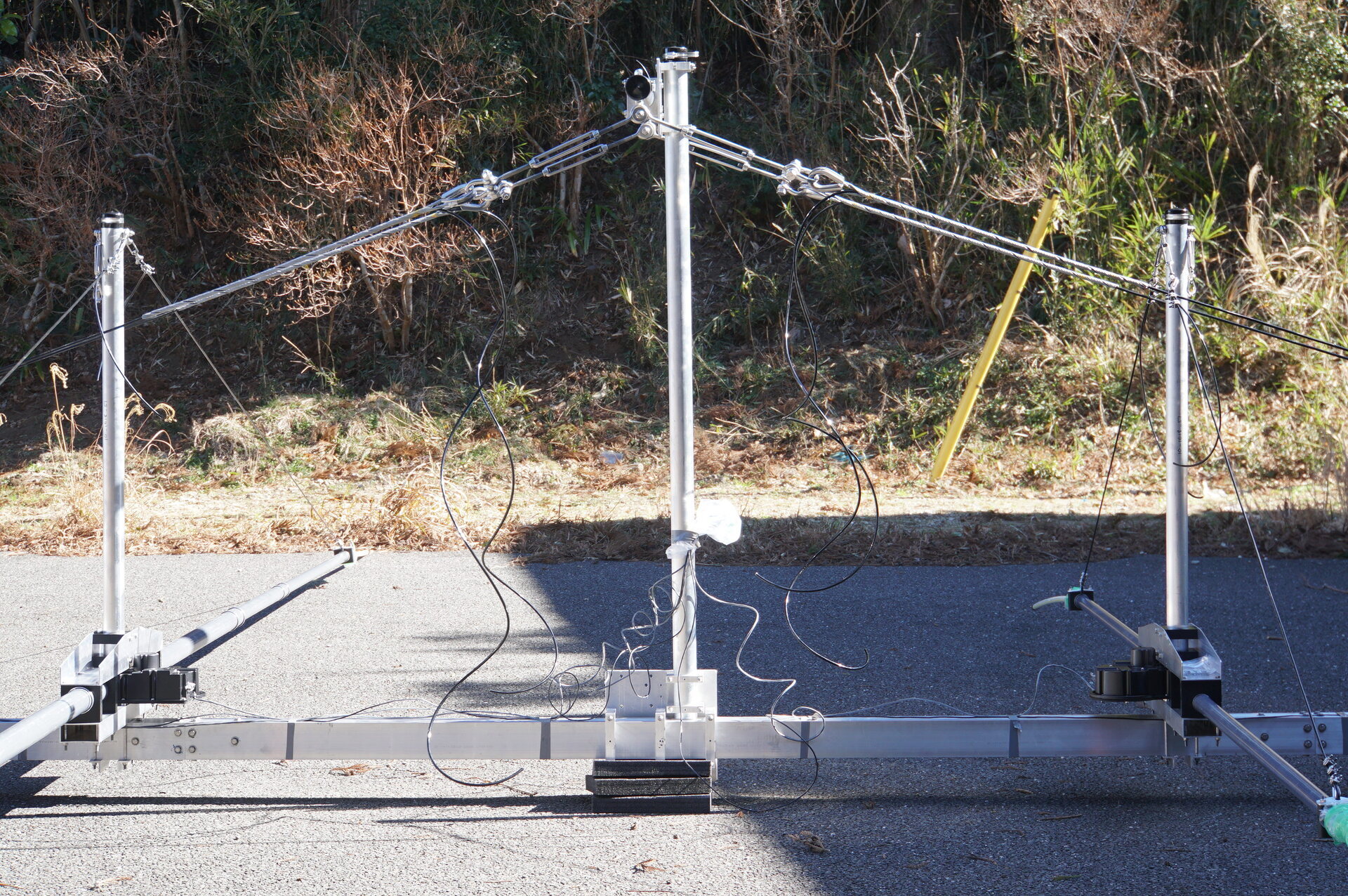
A little closer.
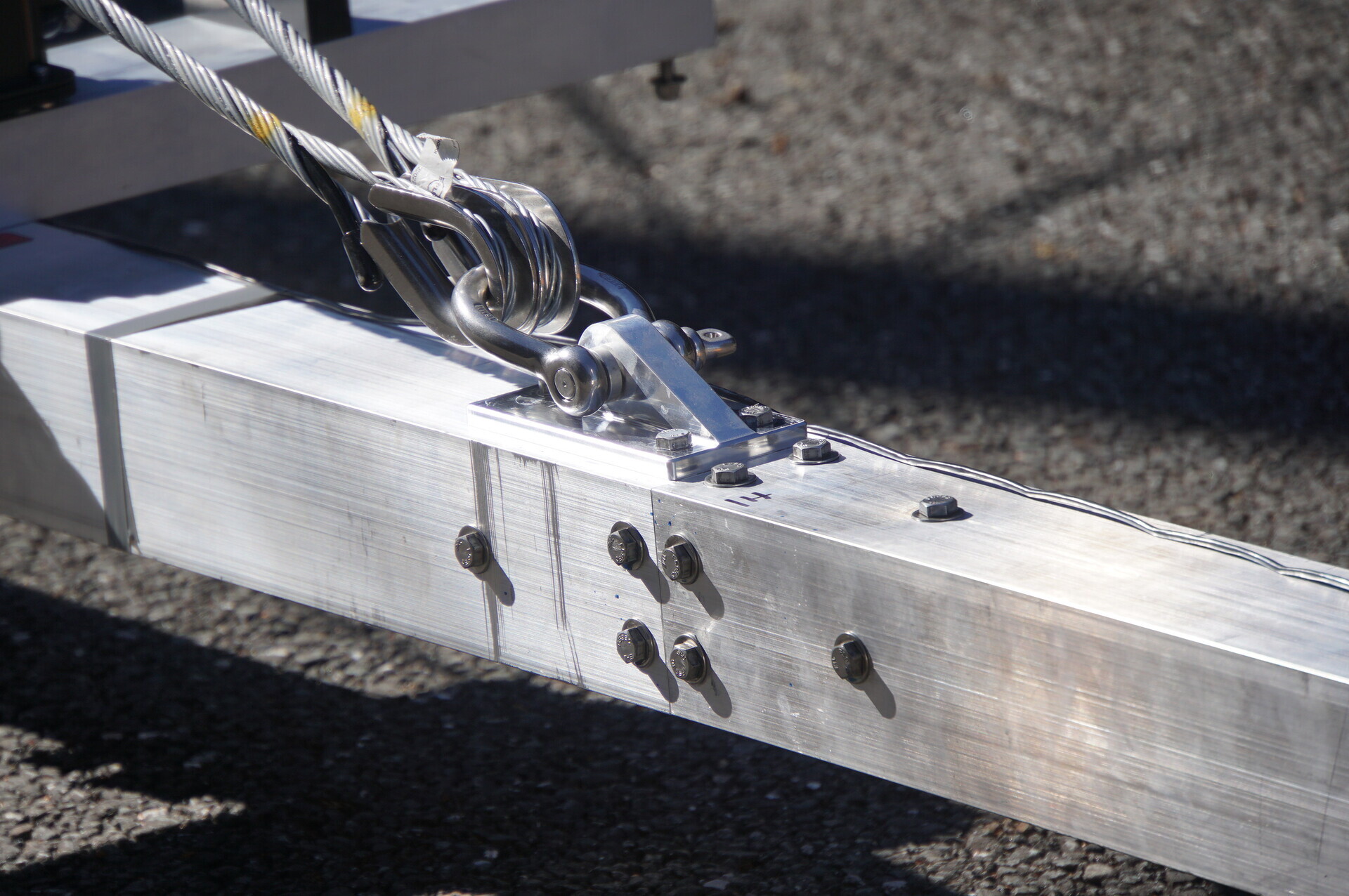
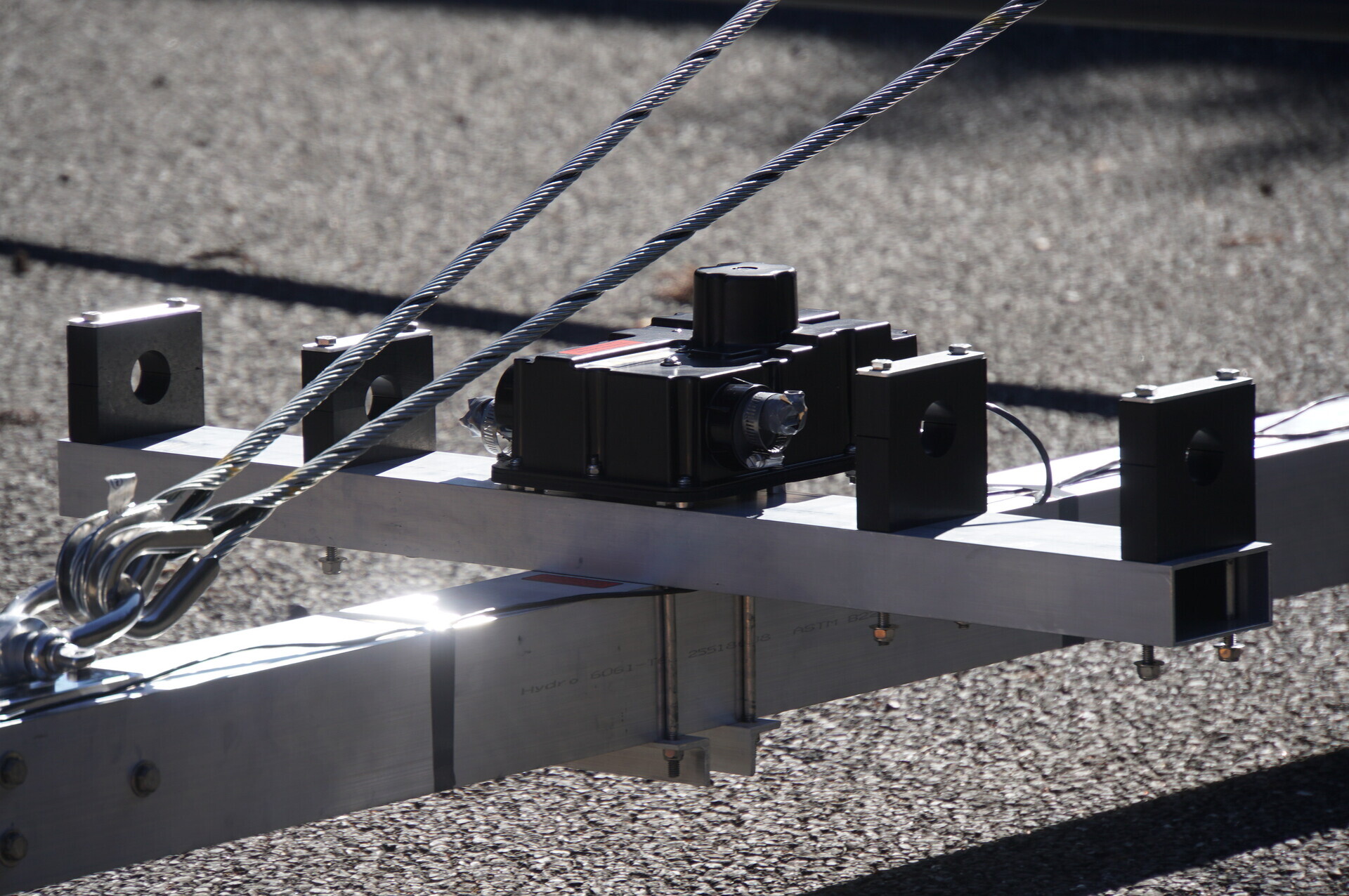
Guys
Supporting the boom.
Each element is suspended too.
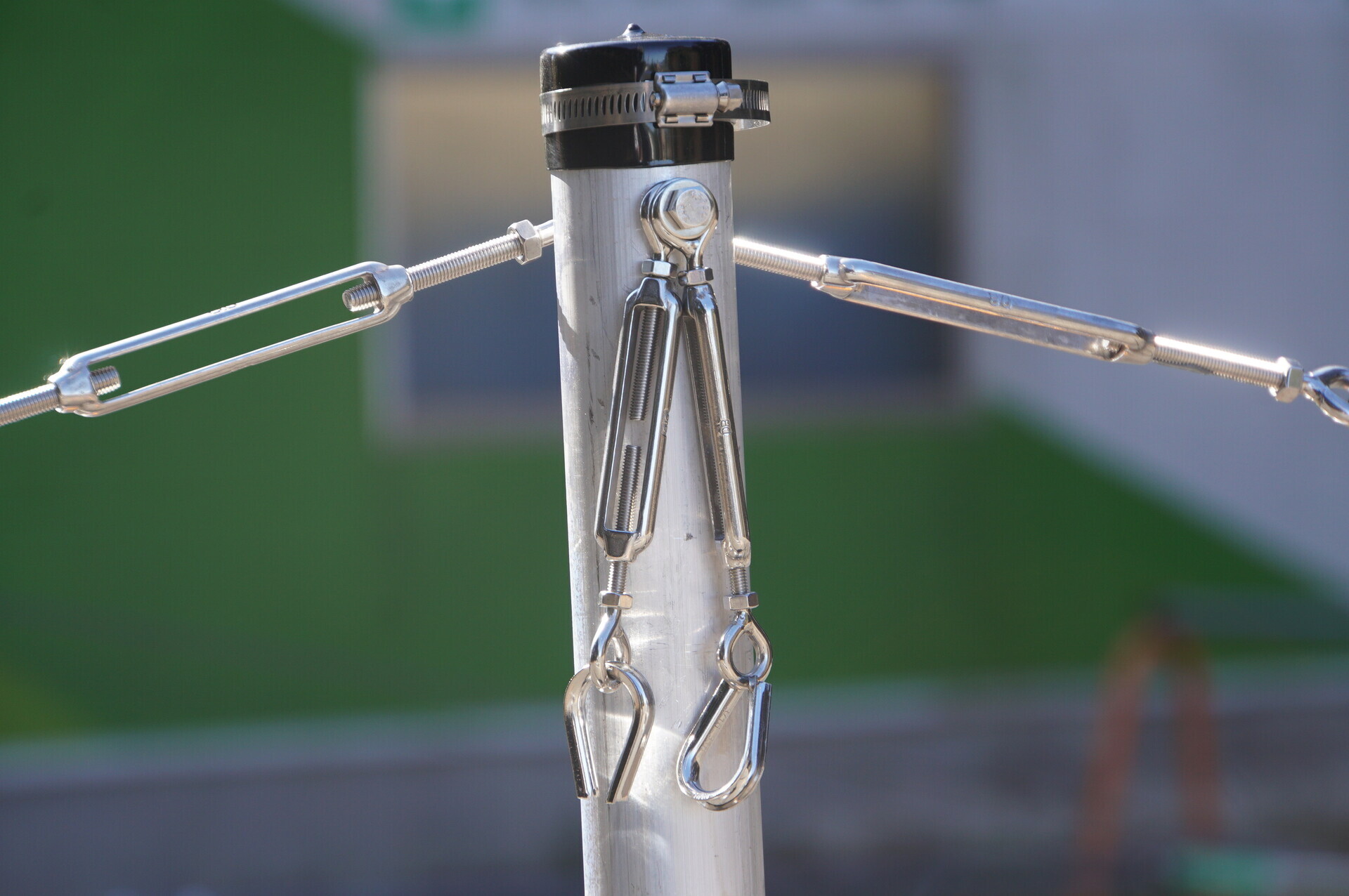
Near an element tip.
Eventually there should be two guys per element side.
Using the turnbuckles hanging loose in the photo above.
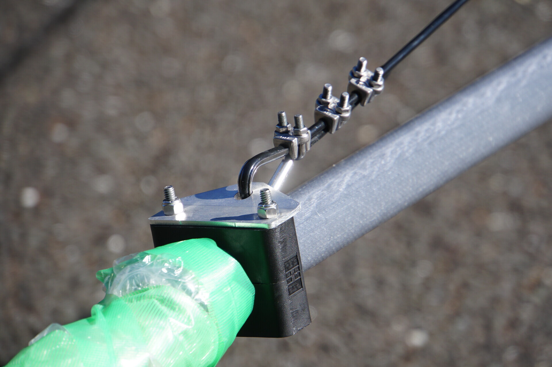
Element attachment
Like this.
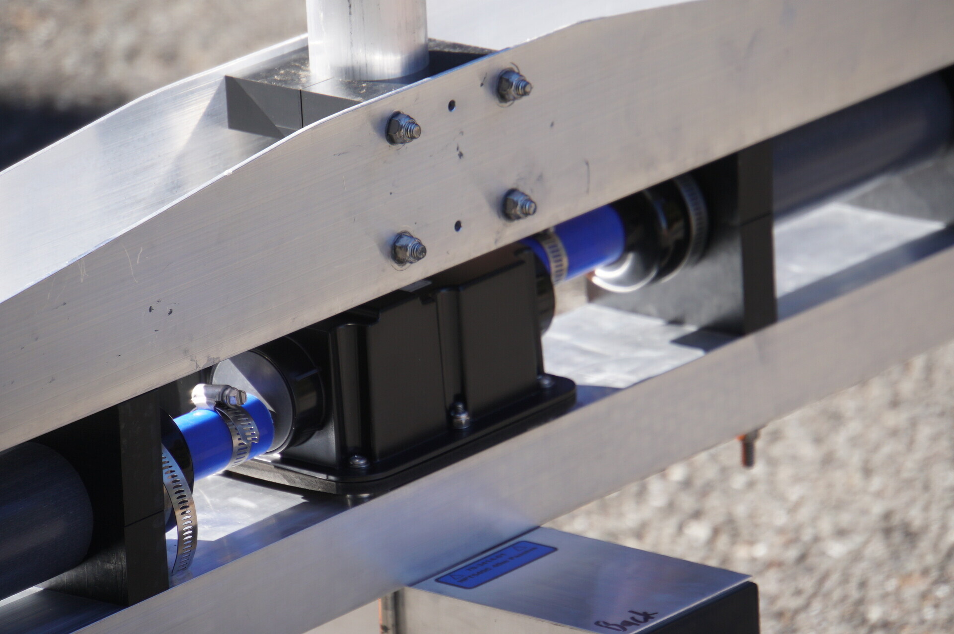
The saddle for the as-yet-unmounted second element from the front.
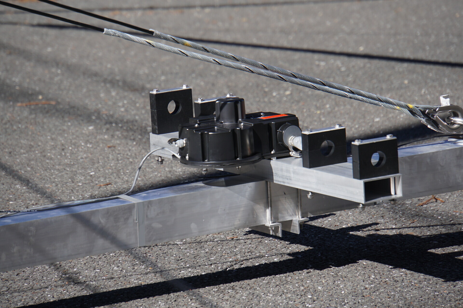
To be continued.