The loop array at Maeda, Minamiboso City
Original: Ryota / JJ1WTL — 515801449 · Original Japanese HTML
Published: 2025-06-01T19:04:00+09:00
English translation of the archived article text. The author’s first-person observations, uncertainty and later additions are preserved; this is not the research summary. Image contents are preserved as images, not silently incorporated into the translated prose.
‘There's another one hiding in a place like that.’
Persistent lunchtime searches of satellite imagery turned up a suspicious site:
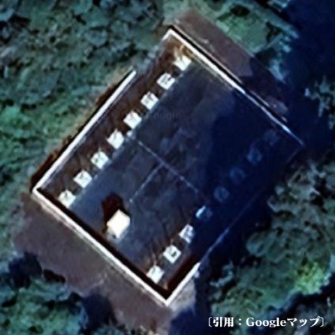
Location
35.03771311690676,139.94242458874854.
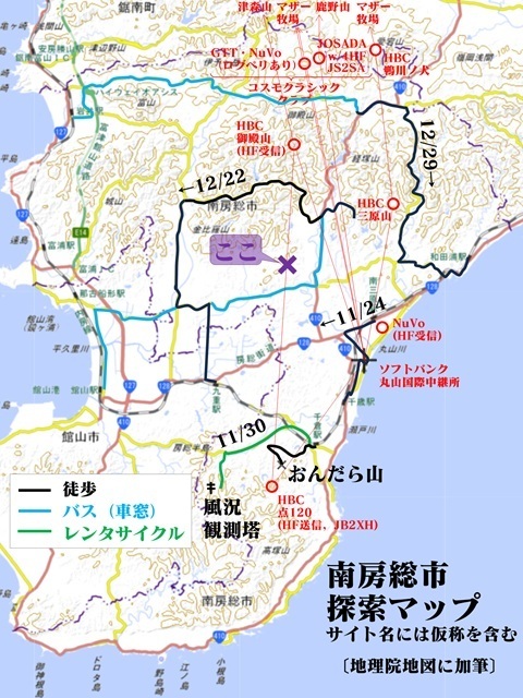
I had passed nearby on the bus during earlier searches, but had not found it.
Because it is in a valley, not on a ridge.
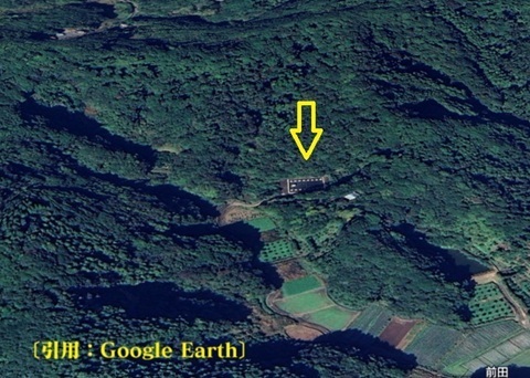
↓ You couldn't possibly spot it from this, could you?
In the end, an update to the satellite imagery was the breakthrough.
Let's go there
‘Visit the scene a hundred times’—Detective Funamura's lesson. Sunday, June 1.
Tamachi 4:52 → Tokyo 5:01 / 5:21 → Kisarazu 6:42 / 6:47 → Tateyama 8:00 / 8:40 → by bus → Maeda 9:13.
First, the train (¥2,310 each way)
Tamachi.
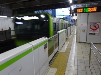
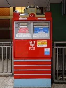
Tokyo. There is a postbox shaped like the station building.
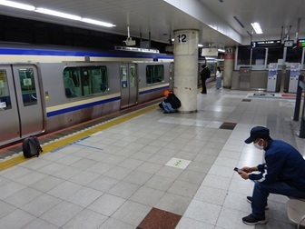
To the underground Sobu Rapid Line platform.
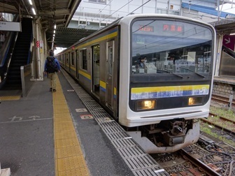
Changing at Kisarazu.
Passing trains at Onuki: waiting for two inbound trains, arrival 7:03, departure 7:11.
Step onto the platform to admire JS2SB from afar. The trick is to ride in the first carriage.
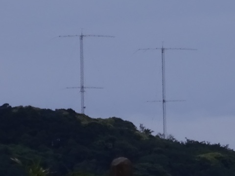
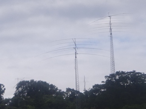
This one is an amateur station, on the left just before Takeoka.
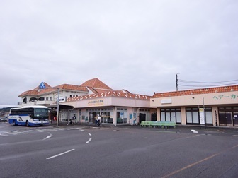
Arriving at Tateyama.
Next, the bus (¥590 each way)
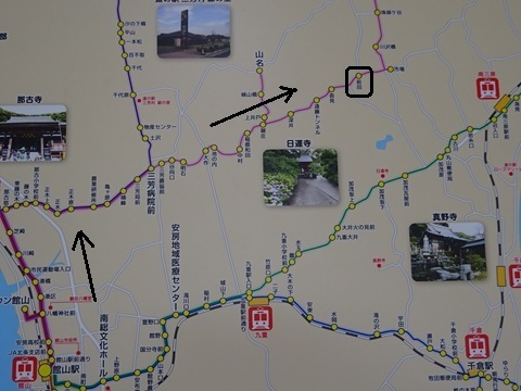
Take the Maru Line to Maeda, boxed in black.
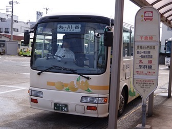
Probably my third time on this bus route in this line of work.
Finally, approach on foot
Heading for that isolated, suspicious Chiba site found in satellite imagery, I begin the search from the nearest settlement! 9:13.
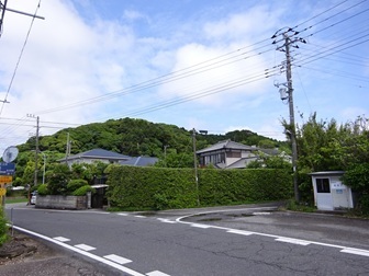
Can't see it… photographed at 9:23.
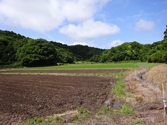
Still can't see it… 9:27.
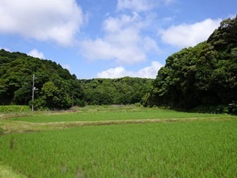
9:29.
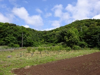
?!(9:29)
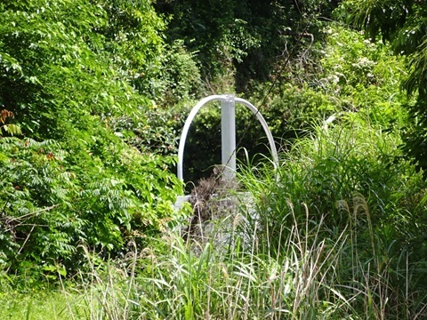
Enjoy the view
Reached it at 9:31.
Overall view
Just right for Radio Day. Click to enlarge (3.2 MB).
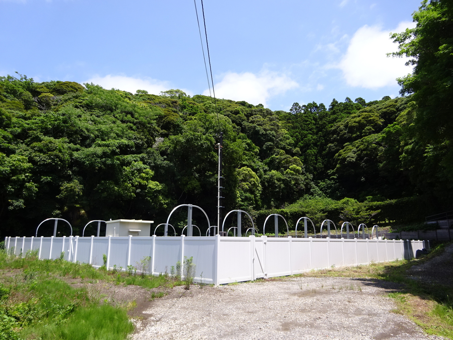
From the rear right of the photo above (3.5 MB).
An 8 × 2 loop array.
The fence is nonmetallic. Each panel is 2 m wide, including the post width.
The loops are spaced 4 m apart: at a wavelength of 40 m, that is 0.1 wavelength. 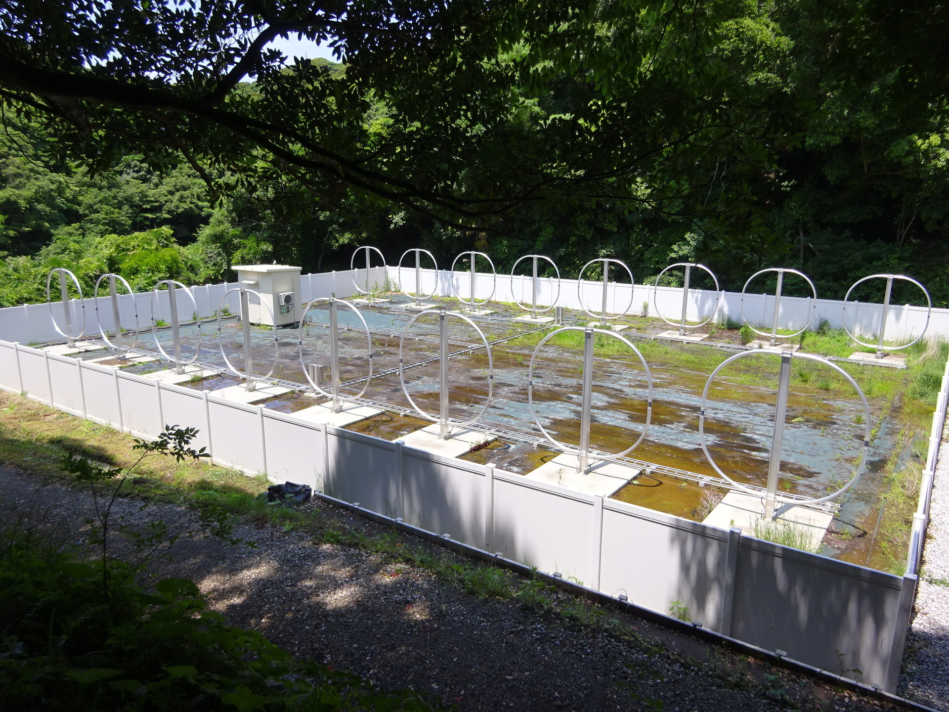
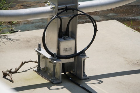
Loop
The whole assembly. Height: 4 m.
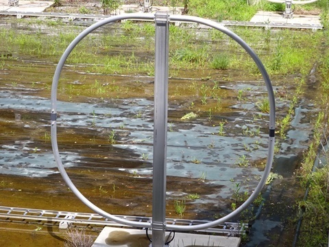
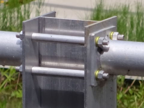
Element mounting, upper section. Electrically connected?
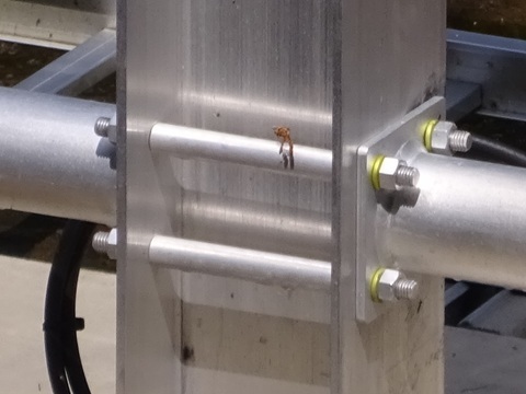
The lower section.
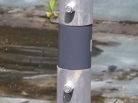
Both sides. Are these insulators?
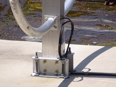
The feed.
[Added June 6 from photographs taken with another camera]
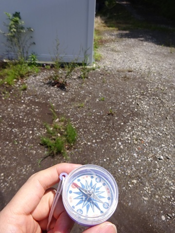
Installation direction
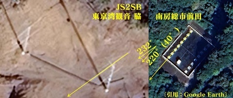
220°.
South of 9V [Singapore]… aimed at 3Y, then.
It is turned farther south even compared with JS2SB.
(Apparently the beam can be steered through phase differences. See the catalogue in the next section.)
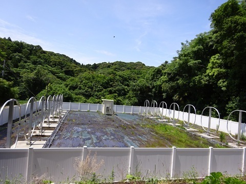
The view toward the southwest looks like this.
There is a slope on the northeast side.
It looks as though there would be losses unless the signals come down at a high elevation angle.
Manufacturer
TCI.
Because: at the base of each loop.
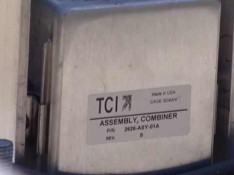
The box at the centre of the row.
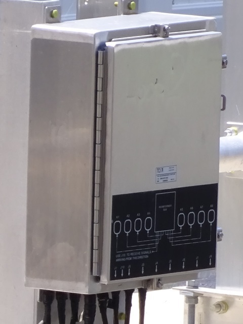
If you want the detailed specifications, consult the catalogue below:
https://www.tcibr.com/wp-content/uploads/2023/06/TCI-612_625-datasheet.pdf
Under the manufacturer's naming convention, the configuration here would be
2-625-8-4-U
—or so I think.
Oh, to state the obvious: this is for reception. This is a receive site.
Among the non-log-periodic antennas known so far in this field—experimental HF digital fixed stations—there are:
(1) JS2SA: the SteppIR one that is not the ‘tape-measure’ type

(2) JS2RB: the added Yagi
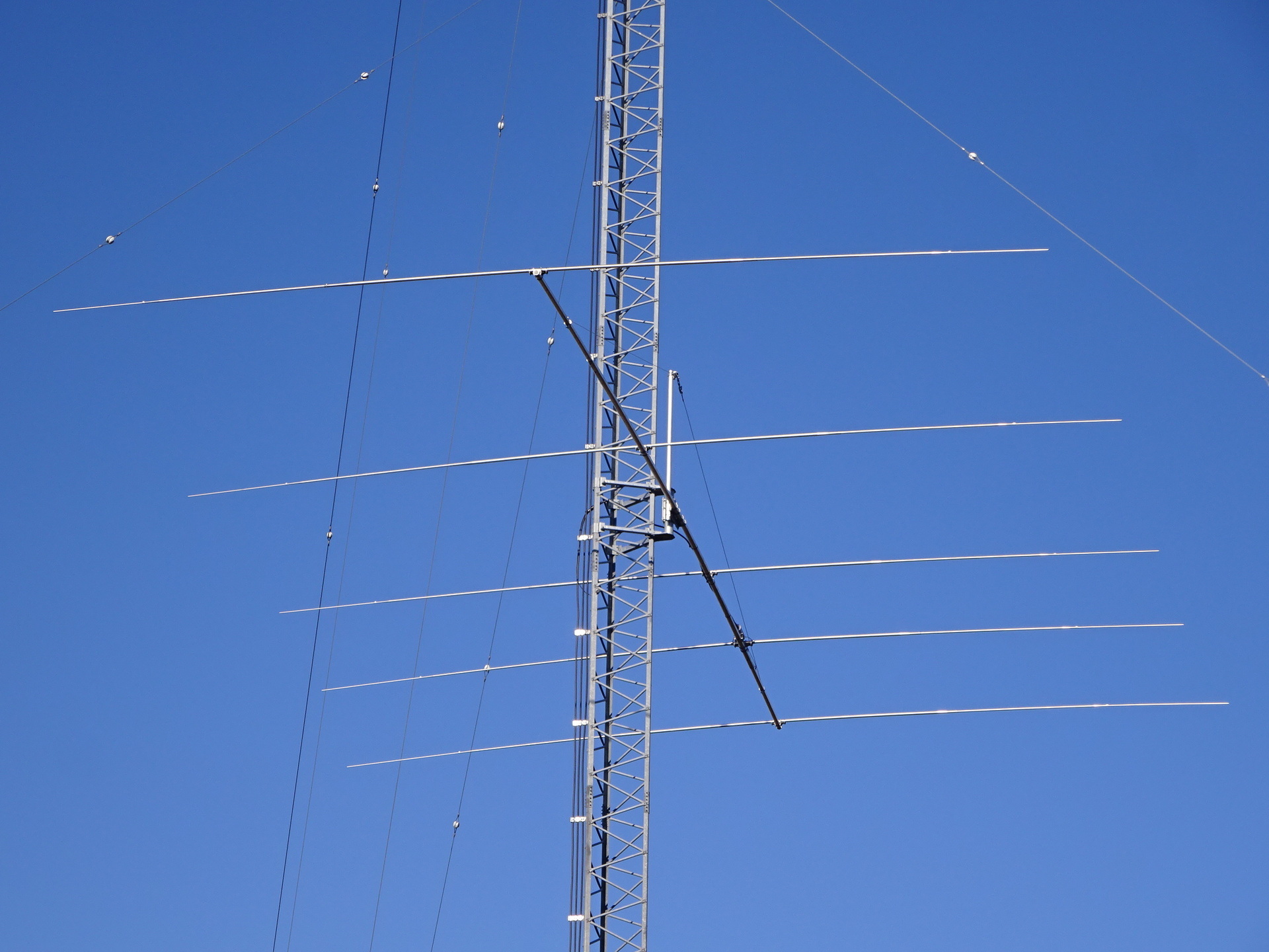
(3) Here: 8 × 2 loop array, receive-only.
Facilities
Station building.
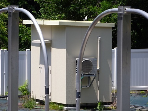
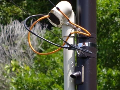
Security camera on the incoming service pole.
GPS ?
Overall view.
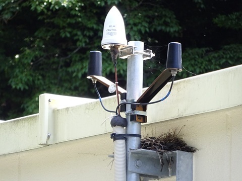
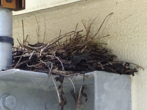
A pointed hat.
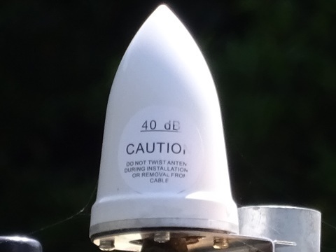
An accessory to the pointed hat?!
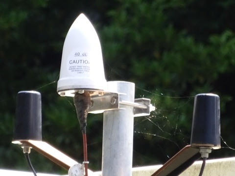
This is a birdhouse, isn't it…
Infrastructure
Looking at the utility pole one pole before the site.
There are homes nearby, and wiring appears to have already existed—the wire extending to the right.
However, it also looks as though an additional electricity phase was installed for this project.
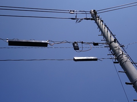
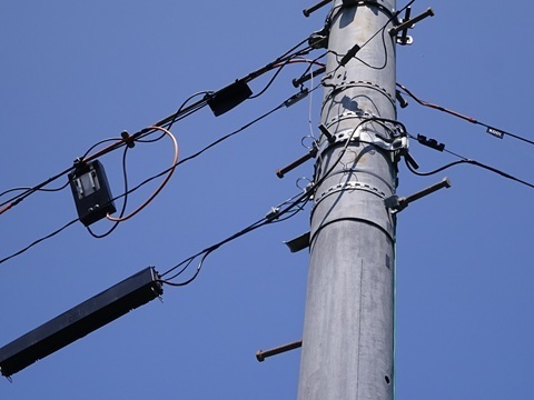
Confirmed: fibre.
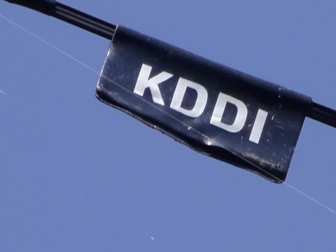
The ‘trunk’ on the upper communications cable—the fibre. The first object counting from the telephone-exchange side.
Perhaps someone from Comsys, Exeo, Mirait One, or a similar company would recognize it.
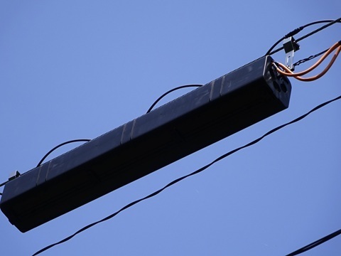
The second object.
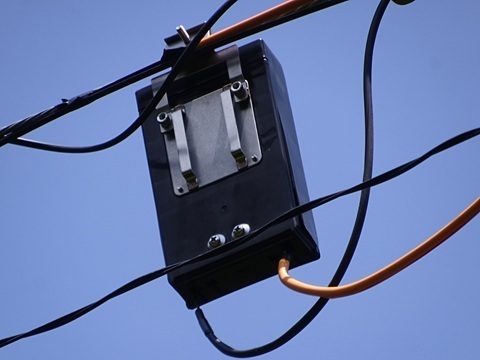
The third object.
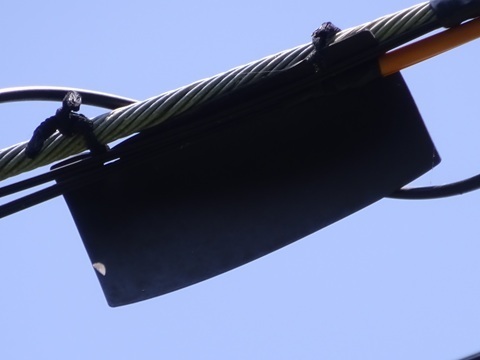
The lower ‘trunk’. The dynamic-loop logo is visible. Is this one copper?
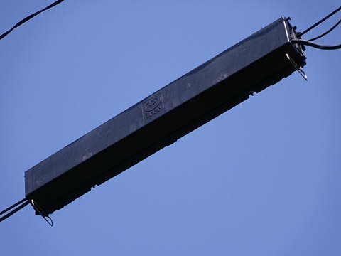
Whose is it?
I checked on site:
Ermis K.K.
In that case, here are the results of the research I had done beforehand.
A search turns up an interesting URL:
https://ermis.jp/en/author/aissamfalcon-ion-io/
This identifies the overseas partner.
Indeed, its website design resembles Ermis's:
Falcon Ion, LLC.
There is no capital relationship, according to the register, so:
-
Not: subsidiary.
-
Yes: business partner.
That is how I will classify it.
Thoughts
Pros
- Broad horizontal directivity.
No need to be terribly precise about the direction.
- If it can operate bidirectionally,
in addition to VS6 [Hong Kong] and 9V [Singapore] to the southwest,
it could target W [USA] to the northeast too, though there is a hill.
- Safe from the standpoint of wind damage.
Surely nobody would be stupid enough to put a log-periodic on a 300 m ridge. After all, there was the 2019 Boso Peninsula Typhoon.

- An electromagnetically quiet location.
- Moist ground.
Close to perfect ground.
- The opposite side of the valley is a northeast-facing slope, so there is little risk of a solar farm being built there.
Cons
- Moist ground: unstable, in a valley.
- A valley makes connection to the central-Tokyo data centres at Toyosu difficult.
If it were me, I would first run fibre south to the SoftBank Maruyama International Relay Station, then turn back from there using a low-latency microwave service.
The penalty for using fibre over that portion would be 15 ns. [Translator's note: ‘ns’ is the unit in the original; it has not been silently corrected.]
Assumption: 4.5 km direct by radio versus 6 km following roads by fibre.
Triumphant return
Maeda 11:57 → late arrival at Tateyama 12:35 / 12:44 → Kimitsu 13:46 / 13:50 → Shimbashi 15:27 / 15:32 → Tamachi.
Home before 16:00.
The same driver as on the way out.
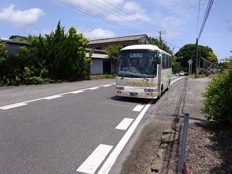
Tateyama.
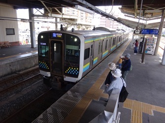
Cross-platform change at Kimitsu.
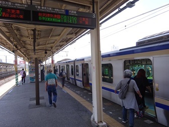
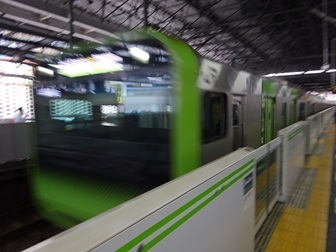
Onto the Yamanote Line at Shimbashi.
Haneda new-line construction report.
The former southbound Keihin-Tohoku tracks have been cut and are being removed.
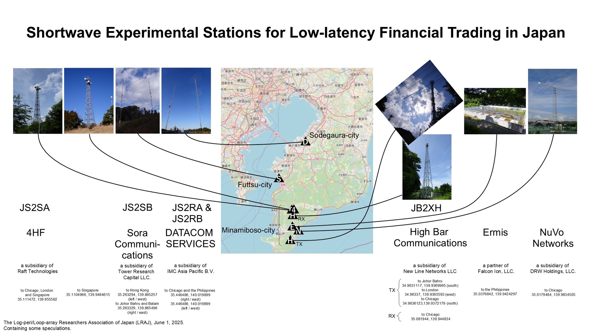
Updated comparison diagram
Click to enlarge, 744 KB.
Earlier posts
‘JS2RA / JS2RB’
https://jj1wtl.seesaa.net/article/499204144.html (English translation)
‘JS2RA / JS2RB, continued’ (additional Philippines-bound Yagi)
https://jj1wtl.seesaa.net/article/505776879.html (English translation)
‘JA/CB-004’ (4HF's JS2SA and HBC's JB2XH, later classified as a receive station)
https://jj1wtl.seesaa.net/article/499505940.html (English translation)
‘JS2SA / JB2XH’
https://jj1wtl.seesaa.net/article/500304565.html (English translation)
‘The new JB2XH’ (transmit station)
https://jj1wtl.seesaa.net/article/504743515.html (English translation)
‘JS2SB’ (licence information)
https://jj1wtl.seesaa.net/article/505386673.html (English translation)
‘JS2SB, continued’ (site photographs)
https://jj1wtl.seesaa.net/article/505597775.html (English translation)
‘JS2SB, continued again’ (building application)
https://jj1wtl.seesaa.net/article/511302814.html (English translation)
‘The Minamihara log-periodic’ (NuVo Networks)
https://jj1wtl.seesaa.net/article/501355072.html (English translation)
‘The log-periodic at Cosmo Classic Club’ (probably GTT)
https://jj1wtl.seesaa.net/article/508688232.html (English translation)
Comments
Translated from the comments in the archived original HTML. Author names and timestamps are retained as displayed; these are separate from the article.
JH5TEY — 2025-06-08 11:35
Hello; I always read your posts with interest. How did you manage to trace this one to Ermis? I look forward to your future investigations!